how to
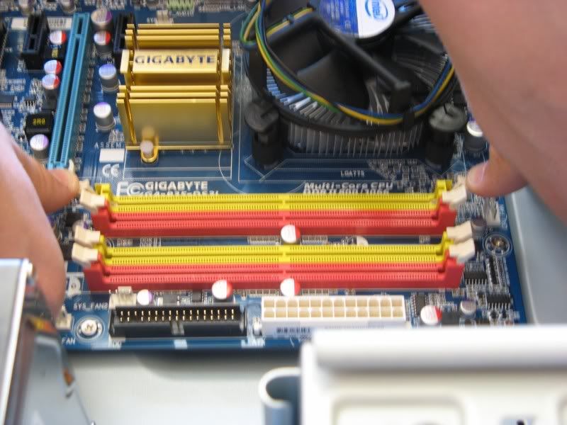
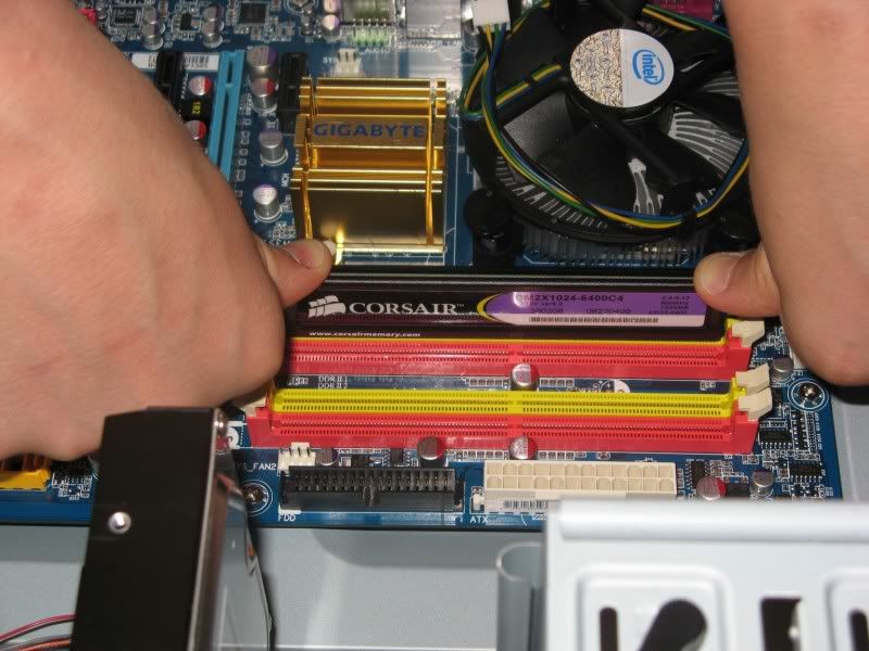
Line the module up (the off-centre notch will ensure it only fits in one way)& use firm pressure to push it in. When it is in place, the slots at the end will have "snapped" into each side of the stick, securing it.
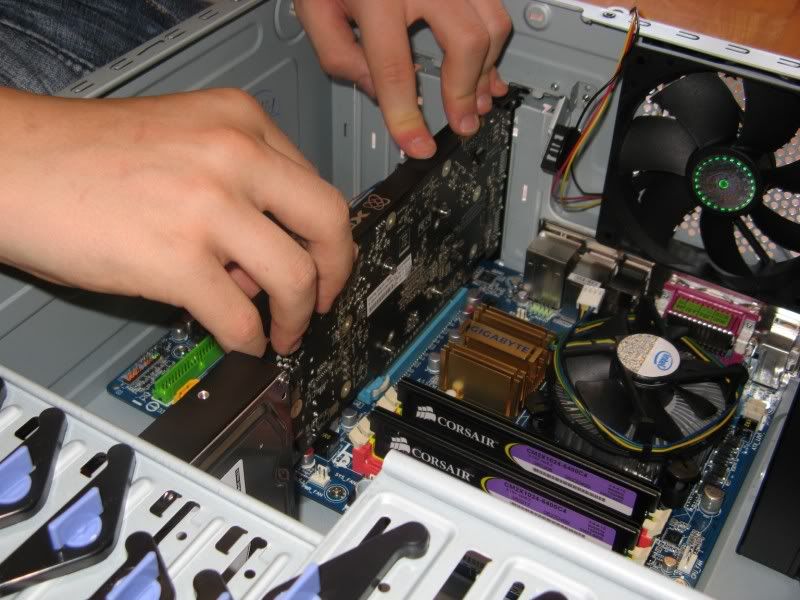
Now add any discrete cards for the build – in our example photo, we have one video card to be installed. Be sure to line up each card properly into the installation slot on the motherboard. Push cards in firm to ensure a proper fit.
Now all the physical components should be installed for your system. All that's left to do is connect everything up. SATA data cables (or IDE ribbon cables for components that connect in that way) need to run from the device to the motherboard. Power cables from the PSU need to connect up to each component as necessary.
It`s important to take care when running the cables from the PSU to each component – always try & get the “mess” minimised as much as possible, for a nicer look & also better in-case airflow. Use zip or cable ties to clean up loose ends, especially where the fans are . It is in this regard that a modular PSU makes all the difference – only connect what is needed and the rest can be left in the box, instead of having to zip tie it all together & put the bundle out of the way as best as is possible... Even so – with careful planning, a non-modular PSU can still be routed efficiently for good air-flow.
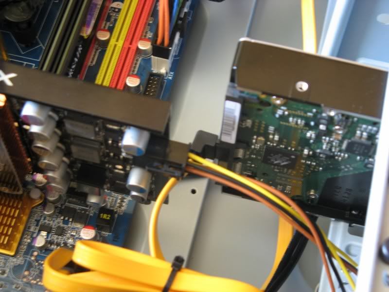
You should have already connected the CPU 4-pin (or 8-pin) connector, so next install the 24-pin ATX motherboard power connector, the DVD drive, the hard drive, the graphics card & anything else in your specific system that needs a power cable.
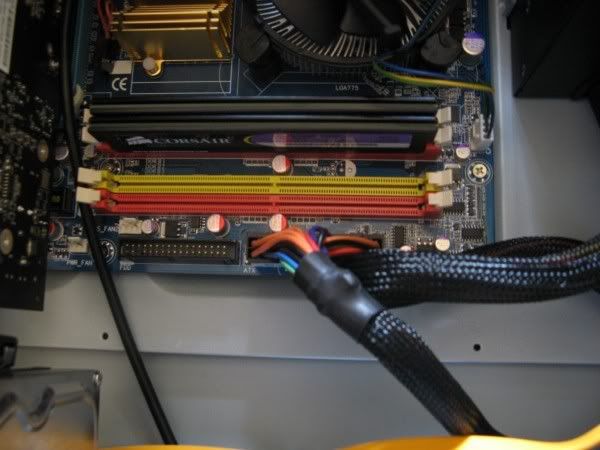
Note from Artellos (Olrik): As you might be able to see, i didn't install the second RAM module in the other Yellow slot. This way the RAM doesn't run in Dual-Channel configuration. I should have placed the second one in the other yellow slot.
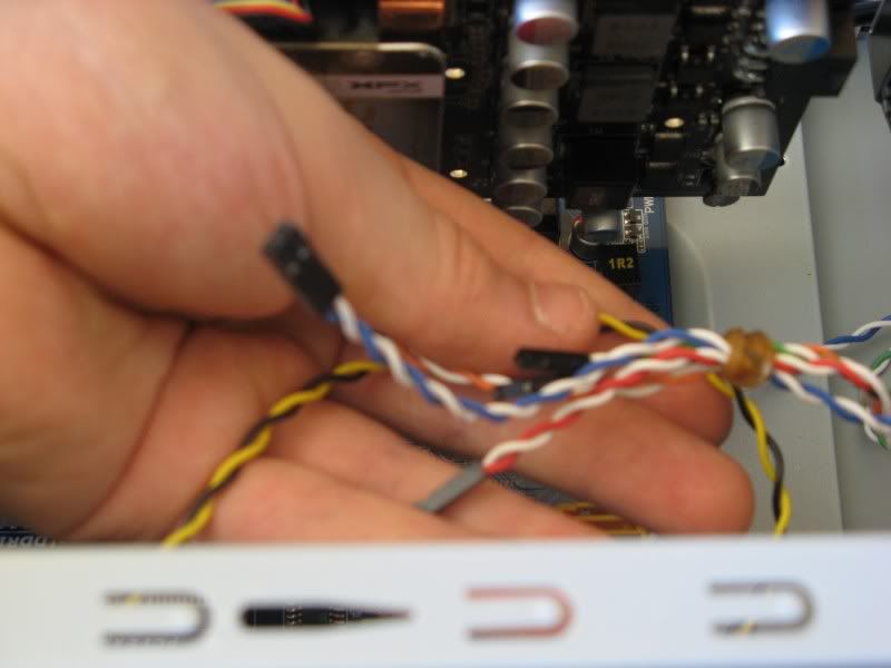
The final connections to be made are the case connectors to the motherboard. These are for the power & reset button, power & HDD light & USB & other data connectors for the ports on the front of the case. As every case & motherboard is different, you'll need to carefully follow the instructions in the motherboard manual. Every manual should have wiring diagrams in detail. You may find it under the heading “Front Panel Connectors” or F_PANEL.
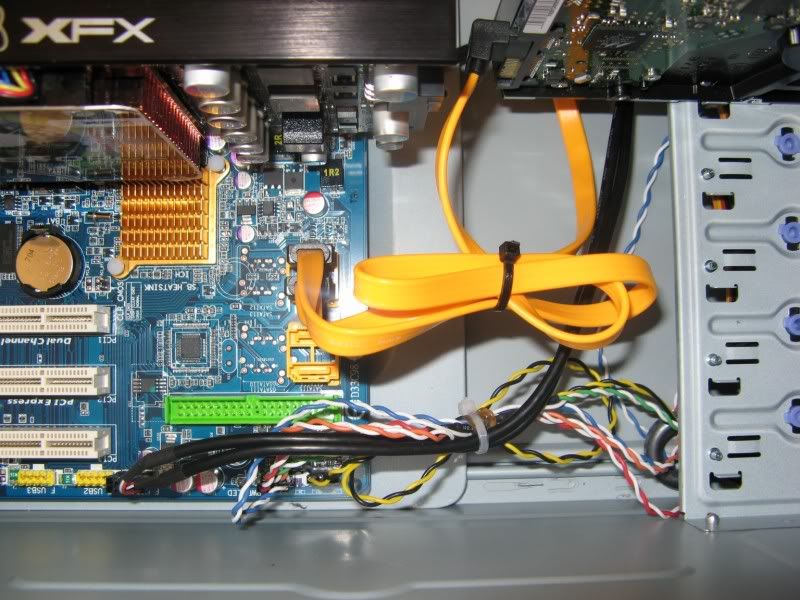
The Photo above is showing a very clean, simple look with the cables tied up nicely
4. The Result
And there you have it. Everything should now be complete, and ready for installation of the operating system. In the photo below, we can see the system in all its glory, although a few more zip-ties to minimise the bunch of black cables from the PSU into a smaller bundle would be nice. Nonetheless, for a first-time build, this Tech Apprentice received top marks!
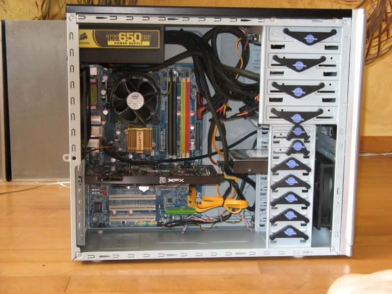
All thats left to do is close the case side panels, to protect the important components inside & to create the proper environment for in-case airflow – to keep all the components nice & cool.
If you are installing an OEM version of Windows, you need to put the COA sticker on the case
That's all there is to it.

No comments:
Post a Comment